
The following tables list the tightening torque for the major fasteners requiring use of a non-permanent locking agent or silicone sealant etc.
Letters used in the “Remarks” column mean: AL: Tighten the two clamp bolts alternately two times to ensure even tightening torque.
G: Apply grease.
L: Apply a non-permanent locking agent.
Lh: Left-hand Threads
MO: Apply molybdenum disulfide oil solution.
(mixture of the engine oil and molybdenum disulfide grease in a weight ratio 10:1)
R: Replacement Parts
S: Follow the specified tightening sequence.
Si: Apply silicone grease (ex. PBC grease).
SS: Apply silicone sealant.


The table below, relating tightening torque to thread diameter, lists the basic torque for the bolts and nuts. Use this table for only the bolts and nuts which do not require a specific torque value. All of the values are for use with dry solvent-cleaned threads.
Basic Torque for General Fasteners

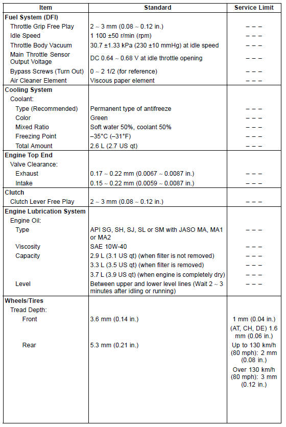
Specifications

Special Tools

 Periodic Maintenance Chart
Shift Drum Assembly
Press and insert the ball bearing [A] on the shift drum [B]
until it is bottomed.
Install:
Ball Bearing [C]
Dowel Pin [D] and Shift Drum Cam [E]
Align the pin with the groove in the shift drum cam.
Apply a non-permanent locking agent to the shift drum
cam holder bolt [F].
Tight ...
Spring Plate Free Play Measurement
Insufficient clutch free play will cause the engine braking
effect to be more sudden, resulting in rear wheel hop. On
the other hand, if the free play is excessive, the clutch lever
may feel “spongy” or pulsate when pulled.
Hold an extra drive shaft in a vise and install the following
c ...
Air Intake Solenoid Valve Unit Test
Remove the air intake solenoid valve (see Air Intake Solenoid
Valve Removal in the Fuel System (DFI) chapter).
Set the hand tester [A] to the × 1 Ω range and connect it
to the air intake solenoid valve terminals as shown in the
figure.
Special Tool - Hand Tester: 57001-1394
...
