
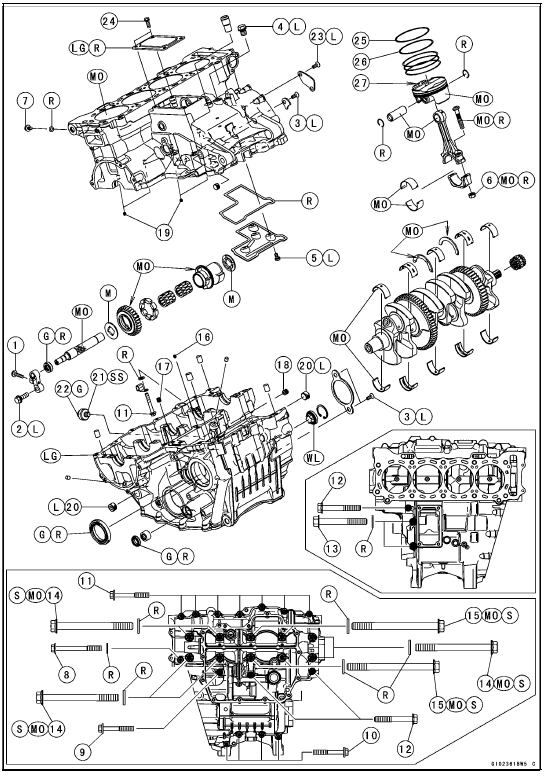

25. “1T” marked side faces up.
26. “T2” marked side faces up.
27. Hollow mark faces exhaust side.
G: Apply grease.
L: Apply a non-permanent locking agent.
LG: Apply liquid gasket.
M: Apply molybdenum disulfide grease.
MO: Apply molybdenum disulfide oil solution.
(mixture of the engine oil and molybdenum disulfide grease in a weight ratio 10:1) R: Replacement Parts
S: Follow the specified tightening sequence.
SS: Apply silicone sealant.
WL: Apply soap and water solution or rubber lubricant.


14. Frame No. JKAZXCJ1CA011772 ∼ G: Apply grease.
L: Apply a non-permanent locking agent.
MO: Apply molybdenum disulfide oil solution.
(mixture of the engine oil and molybdenum disulfide grease in a weight ratio 10:1) R: Replacement Parts
 Specifications
Timing Rotor Installation
Install the timing rotor [A] on the crankshaft [B] with their
teeth [C] aligned.
Holding the timing rotor with the flywheel & pulley holder
and tighten the bolt.
Torque - Timing Rotor Bolt: 39 N·m (4.0 kgf·m, 29 ft·lb)
Special Tool - Flywheel & Pulley Holder: 57001-1605
I ...
Spring Preload Adjustment
The spring preload adjuster is located
at the lower end of each front fork leg
and can be adjusted.
To increase spring preload and
stiffen the suspension, turn the
preload adjuster clockwise with a
hexagon wrench.
To decrease preload and soften the
suspension, turn the preload adjust ...
Crankcase Assembly
NOTICE
The upper and lower crankcase halves are machined
at the factory in the assembled state, so the
crankcase halves must be replaced as a set.
With a high flash-point solvent, clean off the mating surfaces
of the crankcase halves and wipe dry
WARNINGGasoline and low flash-poin ...
